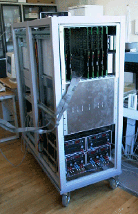
The RASMUS (Remotely Accessible Software configurable Multi-channel Ultrasound Sampling) system consists of four distinct modules: The transmitters, the analog amplifiers (Rx/Tx amplifiers), receivers, and the sync/master unit.
RASMUS seen from the front with the receivers on the top, transmitters in the middle and power supplies in the bottom. Two 19 inch racks house the eight transmitters and the eight receivers, respectively. Each of the racks also house a slot PC running Linux controlling the setup and operation of the boards. A separate enclosure is used for the analogue front-end, which is shielded from the digital electronics. Linear laboratory power supplies are also used to supply the front-end to keep the noise low.
Each transmitter board has 16 channels consisting of a 128 ksamples RAM connected to a 40 MHz, 12 bits DAC. The RAM is controlled by an FPGA (Field Programmable Gate Array), where the individual waveforms are selected as a memory start address and a transmit delay. The waveform as well as the delay can change for each emission ensuring full flexibility in the transmissions. The length of the waveforms can be set and waveform durations up to 100 microseconds can be emitted. The system houses eight boards for a total of 128 independent emission channels.
 The receiver board layout without RAM modules to reveal the processing electronics. Board size is 53 cm by 36.5 cm. It samples and processes 8 analogue signals selected from 16 inputs through a 2-to-1 multiplexer. Each of the input signals is sampled at 40 MHz and 12 bits into one of the two SRAMs. One SRAM is used for ampling, the second for transferring data to the Focus FPGA associated with each channel. The data is then processed in the Focus FPGA using parameters from the 128 MBytes Focusing RAM, and the result is passed on to the Sum FPGA. The processing can either be a dynamic receive focusing or the data can be passed unaltered for later storage. The Sum FPGA can either store the data in the 2Gbytes storage RAM or it can sum all eight channels with the result from the cascade bus and pass it on to the next receiver board through the cascade bus. The last receiver board in the system then transmits the focused signal to the ADSP SHARC for transmission to the display PC.
The storage RAM can contain more than three seconds of real time data for each channel, which can later be accessed from the PC's controlling the system. All boards have a size of 53 by 36.5 cm, and the receiver is manufactured using 12 layers.